System Install MagicDAQ

MagicDAQ Hardware

To use this API, you will need the MagicDAQ hardware, which you can find at magicdaq.com

Python 3 on Windows Only

MagicDAQ must be run with Python 3 on Windows. MagicDAQ is downloaded using pip.

  • You can download the latest version of Python here
  • Don’t forget to add Python to the Windows PATH
  • MagicDAQ only works on Windows. Linux and Mac are not supported due to hardware driver constraints.

You can test if your system is ready to go by opening a command prompt and entering:

python -m pip

You are ready to download MagicDAQ if you get back something like the following:

Usage:
  C:\Users\srh\AppData\Local\Programs\Python\Python36\py3.exe -m pip <command> [options]

Commands:

If you see something different, please check that pip is installed and working.

If you need a bit of help getting started with MagicDAQ, feel free to email us at:

support@magicdaq.com

Install MagicDAQ with Pip

To install MagicDAQ for the first time, open a command prompt and enter:

python -m pip install magicdaq

To upgrade an existing instillation of MagicDAQ, open a command prompt and enter:

python -m pip install magicdaq --upgrade

  • MagicDAQ is hosted on PyPi. The PyPi page shows the latest version number for the MagicDAQ package.
  • To see install debug output, add -v to the end of above command

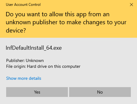
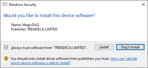
Authorize Driver Install

If this is your first time installing MagicDAQ, you will need to allow MagicDAQ to install its driver on your computer.

  • During the instillation process, two pop ups will appear - please approve them.

Alt Text

Alt Text

System CODE EXAMPLE Check MagicDAQ Install

You can check that MagicDAQ is installed properly by running the following code.

  • It is not necessary to have MagicDAQ connected to the computer in order to run this code

Example Code

Source File


# This script checks that the MagicDAQ API and MagicDAQ Driver were installed properly
# It is NOT NECESSARY to have the MagicDAQ connected to the computer

print('*** MagicDAQ Install Check***')
print('')

try:

    # Import MagicDAQDevice object
    from magicdaq.api_class import MagicDAQDevice

    # Create daq_one object
    daq_one = MagicDAQDevice()
    print('GOOD: MagicDAQ API is installed properly.')

    # Get MagicDAQ Driver Version
    driver_version = daq_one.get_driver_version()

    if driver_version == 1.0:
        print('GOOD: MagicDAQ Driver is installed properly.')
        print('You are ready to use MagicDAQ!')
    else:
        print('ERROR: MagicDAQ Driver version not expected value: '+str(driver_version))
        print('Try installing MagicDAQ using pip again.')
        print('https://magicdaq.github.io/magicdaq_docs/#/Install_MagicDAQ')
        print('Feel free to email MagicDAQ Support at: support@magicdaq.com')

except Exception as exception_text:
    print('Original exception: ')
    print(exception_text)
    print('')
    print('ERROR: Unable to import MagicDAQ API.')
    print('Mostly likely, MagicDAQ has not been properly downloaded and installed using pip.')
    print('Please consult MagicDAQ API Docs: https://magicdaq.github.io/magicdaq_docs/#/Install_MagicDAQ')
    print('Feel free to email MagicDAQ Support at: support@magicdaq.com')

print('')
print('*** MagicDAQ Install Check Completed***')

Expected Output


GOOD: MagicDAQ API is installed properly.
GOOD: MagicDAQ Driver is installed properly.
You are ready to use MagicDAQ!

MagicDAQ Hardware Check

Connect the MagicDAQ to the computer using the USB cable.

  • If the driver is installed properly, you will see the red LED power light on the top of the DAQ pulsing.
  • If the driver is not installed, the red LED power light will be constantly on.

System CODE EXAMPLE MagicDAQ Hello World Example

Import MagicDAQDevice Object

Every Python script must import the MagicDAQDevice object.

from magicdaq.api_class import MagicDAQDevice

All features of the MagicDAQDevice are accessed by creating a MagicDAQDevice object and calling methods on this object.

  • Create MagicDAQDevice object
  • Open the DAQ with open_daq_device()
  • Do useful things with the DAQ by calling methods on the object
  • Close the DAQ with close_daq_device()

Hello World Example Code

Source File


# Use the USB cable to plug MagicDAQ into your computer

# Import MagicDAQDevice object
from magicdaq.api_class import MagicDAQDevice

# Create daq_one object
daq_one = MagicDAQDevice()

# Connect to the MagicDAQ
daq_one.open_daq_device()

# Do useful things with the DAQ
# For example, you can read a digital pin's state
print('This is Digital Pin P0.0 State: '+str(daq_one.read_digital_input(0)))

# We are done using the MagicDAQ, so close it
daq_one.close_daq_device()

Expected Output

This is Digital Pin P0.0 State: 1

System open_daq_device()

Method opens a daq device for utilization.

Definition

open_daq_device(daq_serial_num = None)

Optional Arguments

  • daq_serial_num: str DAQ Serial Number. When supplied, open_daq_device connects to the specified device.

System close_daq_device()

Method closes the DAQDevice. Call this method after you are finished using the DAQ device.

  • In order to use the DAQ hardware again, you will have to call the open_daq_device() method.

Definition

close_daq_device()

System CODE EXAMPLE MagicDAQ / M&A Board Feature Demo

The below script is a guided tour through most of the USB DAQ’s features. If you have an M&A Board, you can connect it to the MagicDAQ to test some of its features as well.

Demo Code

Source File


##############################################################
#*** MagicDAQ USB DAQ and M&A Board General Demo Script ***
##############################################################

#*** Websites ***
# MagicDAQ Website:
# https://www.magicdaq.com/
# API Docs Website:
# https://magicdaq.github.io/magicdaq_docs/

#*** Install MagicDAQ ***
# Download the MagicDAQ python package from pypi
# Run this command in a command prompt:
# python -m pip install magicdaq
# Further docs: https://magicdaq.github.io/magicdaq_docs/#/Install_MagicDAQ
# MagicDAQ is only compatible with Python 3 on Windows. It does not work on Linux at the moment. It does not work with Python 2.

#*** Using Auto Code Complete With PyCharm ***
# Using a code editor like Pycharm and want to get auto complete working for the MagicDAQ package?
# Docs: https://magicdaq.github.io/magicdaq_docs/#/PyCharmCodeCompletion

##############################################################
#*** Imports ***
##############################################################

import sys
import time

# Import MagicDAQ
print('*** MagicDAQ Install Check ***')
print('')

try:

    # Import MagicDAQDevice object
    from magicdaq.api_class import MagicDAQDevice

    # Create daq_one object
    daq_one = MagicDAQDevice()
    print('GOOD: MagicDAQ API is installed properly.')

    # Get MagicDAQ Driver Version
    driver_version = daq_one.get_driver_version()

    if driver_version == 1.0:
        print('GOOD: MagicDAQ Driver is installed properly.')
        print('You are ready to use MagicDAQ!')
    else:
        print('ERROR: MagicDAQ Driver version not expected value: '+str(driver_version))
        print('Try installing MagicDAQ using pip again.')
        print('https://magicdaq.github.io/magicdaq_docs/#/Install_MagicDAQ')
        print('Feel free to email MagicDAQ Support at: support@magicdaq.com')

except Exception as exception_text:
    print('Original exception: ')
    print(exception_text)
    print('')
    print('ERROR: Unable to import MagicDAQ API.')
    print('Mostly likely, MagicDAQ has not been properly downloaded and installed using pip.')
    print('Please consult MagicDAQ API Docs: https://magicdaq.github.io/magicdaq_docs/#/Install_MagicDAQ')
    print('Feel free to email MagicDAQ Support at: support@magicdaq.com')
    sys.exit(0)


##############################################################
#*** MagicDAQ USB DAQ MDAQ300 Features Demo ***
##############################################################

# This portion of the script shows off some of the USB DAQ's features
# Hardware docs: https://www.magicdaq.com/product/magic-daq/

print('')
print('*** MagicDAQ USB DAQ Demo ***')
print('Ensure the USB DAQ is plugged into the computer using the USB cable.')
print('The DAQ does not need to be connected to the M&A board.')
print('')
user_input = input('Press any key to continue.')

#*** Open DAQ Device ***

# Remember, the daq_one object has already been created in the above 'Imports' section
# We must open the daq device before performing any hardware feature manipulation
# https://magicdaq.github.io/magicdaq_docs/#/MagicDAQ_Basics
daq_one.open_daq_device()


###############################################################
#*** Analog Output Demo: Constant, Sine, and PWM on AO1 Pin ***
###############################################################

print('')
print('--- Analog Output Demo: Constant, Sine, and PWM Output ---')

# Set constant 3 volt output voltage on AO1 pin
daq_one.set_analog_output(1,3)

print('Using an oscilloscope, place the scope probe on pin AO1 and connect the scope probe GND to one of the USB DAQs AGND pins')
print('You should now observe a constant 3V')
print('')
user_input = input('Press any key to continue.')

# Configure and start 300Hz sine wave with 2V amplitude on AO1 pin
daq_one.configure_analog_output_sine_wave(1,300,amplitude=2)
daq_one.start_analog_output_wave(1)
print('You should now observe a 300Hz sine wave with 2V amplitude.')
print('')
user_input = input('Press any key to continue.')

# Stop previous wave
daq_one.stop_analog_output_wave(1)

# Configure and start PWM wave, 200 Hz, 50% duty cycle, 3.3V amplitude
daq_one.configure_analog_output_pwm_wave(1,200,50,amplitude=3.3)
daq_one.start_analog_output_wave(1)
print('You should now observe a 200Hz PWM wave, 50% duty cycle, with 3.3V amplitude.')
print('')
user_input = input('Press any key to continue.')

# Stop the wave
daq_one.stop_analog_output_wave(1)
print('The wave should now stop. You could set it to GND using set_analog_ouput() if you wanted.')
print('')
user_input = input('Press any key to continue.')


###############################################################
#*** Pulse Counter Pin Demo: PWM waves ***
###############################################################

print('')
print('--- Pulse Counter Pin Demo: PWM Waves ---')

# Configure a 50 KHz frequency, 75% duty cycle, continuous PWM Wave on the counter pin (CTR0)
# Note that unlike the analog output pins, the CTR0 pin always outputs at an amplitude of 3.3v when producing PWM waves
daq_one.configure_counter_pwm(50000,75)
# Start counter wave
daq_one.start_counter_pwm()

print('Place your scope probe on pin CTR0')
print('You should see a 50kHz, 75% duty cycle PWM wave.')
print('')
user_input = input('Press any key to continue.')

# Now stopping the counter PWM wave
daq_one.stop_counter_pwm()
print('The PWM wave will now stop.')
print('')
user_input = input('Press any key to continue.')


###############################################################
#*** Pulse Counter Pin Demo: Pulse Counting ***
###############################################################

print('')
print('--- Pulse Counter Pin Demo: Pulse Counting ---')

print('Use a piece of wire to bridge CTR0 to DGND several times')
print('CTR0 has an internal pull up resistor. You are simulating a pulse pulling the voltage to GND.')
print('You will have 8 sec to simulate some pulses.')
print('')
user_input = input('Press any key when you are ready to start.')

# Start the Pulse Counter
# Pulses will be counted on the falling edge
daq_one.enable_pulse_counter()

# Sleep for 8 sec
time.sleep(8)

# Read number of pulses
print('Number of pulses counted: '+str(daq_one.read_pulse_counter()))
print('You are using a piece of wire, so it is likely bouncing on and off the screw terminal, counting many pulses')

print('')
user_input = input('Stop simulating pulses. Press any key to continue.')
print('')
print('Now clearing the pulse counter')
daq_one.clear_pulse_counter()
print('Pulse count after clearing: '+str(daq_one.read_pulse_counter()))


###############################################################
#*** Digital Pin Demo ***
###############################################################

print('')
print('--- Digital Pin Demo ---')

# Set P0.0 pin LOW
daq_one.set_digital_output(0,0)
print('Place scope probe on pin P0.0, pin should be LOW')
print('')
user_input = input('Press any key to continue.')

# Set P0.0 pin HIGH
daq_one.set_digital_output(0,1)
print('Place scope probe on pin P0.0, pin should be HIGH')
print('')
user_input = input('Press any key to continue.')


###############################################################
#*** Analog Input Pin Demo ***
###############################################################

print('')
print('--- Analog Input Pin Demo ---')

# Single ended voltage measurement
print('Apply voltage to AI0 pin. If you dont have a power supply handy, you can run a wire from the +5V pin to the AI0 pin.')
print('')
user_input = input('Press any key to continue.')
print('Voltage measured at AI0: '+str(daq_one.read_analog_input(0)))
print('If you are using the +5V pin, remember that this voltage is derived from the USB Power supply, so it will be what ever your USB bus ir producing, probably something slightly less than 5V.')

# If you want to perform a differential input measurement
# daq_one.read_diff_analog_input()
# https://magicdaq.github.io/magicdaq_docs/#/read_diff_analog_input


###############################################################
#*** M&A Board Demo ***
###############################################################

# M&A Board hardware spec:
# https://www.magicdaq.com/product/ma-board-full-kit/

print('')
print('*** M&A Board Demo ***')
print('Ensure the USB DAQ is connected to the M&A board using the ribbon cable.')
print('Ribbon cable pin out on page 6 of: ')
print('https://www.magicdaq.com/mdaq350datasheet/')
print('Use the provided power cable to apply power to the M&A board.')

print('')
user_input = input('Press any key to continue.')


###############################################################
#*** Relay Demo ***
###############################################################

print('')
print('--- Relay Demo ---')

print('Setting all relays to closed.')
daq_one.set_digital_output(7, 1)
daq_one.set_digital_output(6, 1)
daq_one.set_digital_output(5, 1)
daq_one.set_digital_output(4, 1)
time.sleep(1)

relay_count = 1
digital_pin_count = 7

while relay_count <= 4:
    print('Relay #: ' + str(relay_count) + ' Digital Pin #: ' + str(digital_pin_count))

    # Set relay to open
    print('Setting relay to OPEN.')
    daq_one.set_digital_output(digital_pin_count, 0)
    time.sleep(1)

    # Increment counters
    relay_count += 1
    digital_pin_count -= 1

    print('')

print('')
user_input = input('Press any key to continue.')


###############################################################
#*** Vout Demo ***
###############################################################

print('')
print('--- Vout Demo ---')
print('Vout provides a variable voltage power output capable of up to 2A')
print('By characterizing your M&A board, or building a feedback loop; voltage accuracy of Vout can be made quite good.')
print('See notes on page 4 of the M&A data sheet.')
print('https://www.magicdaq.com/mdaq350datasheet/')

# See the M&A board data sheet for the equation that describes the Vout to Vout_set (0 and 2.77 here) relationship

print('')
print('Vout_set Set to 0V.')
print('Measure Vout with a multimeter. It should be about 10V')
daq_one.set_analog_output(0, 0)

print('')
user_input = input('Press any key to continue.')

print('Vout_set Set to 2.77V')
print('Measure Vout with a multimeter. It should be about 5V')
daq_one.set_analog_output(0, 2.77)
print('')
user_input = input('Press any key to continue.')


###############################################################
#*** Low Current Measurement Demo: A1 ***
###############################################################
print('')
print('--- A1 Low Current Measurement Demo ---')
print('Use the 3.3V board voltage and a 20K resistor to put 165uA through A1.')
print('')
user_input = input('Press any key to continue.')

# See the M&A board data sheet for the equation that describes the Vout to current relationship

pin_4_voltage = daq_one.read_analog_input(4)
print('Read voltage: ' + str(pin_4_voltage))
calculated_current_amps = pin_4_voltage / (332 * 97.863)
ua_current = round((calculated_current_amps / .000001), 3)
print('Calculated uA current: ' + str(ua_current))


###############################################################
#*** Current Measurement Demo: A2 ***
###############################################################
print('')
print('--- A2 Current Measurement Demo (+/- 5A max) ---')
print('Use an external 5V power supply and 5 ohm power resistor to put 1 Amp through A2.')
print('')
user_input = input('Press any key to continue.')

# See the M&A board data sheet for the equation that describes the Vout to current relationship

pin_5_voltage = daq_one.read_analog_input(5)
print('Read voltage: ' + str(pin_5_voltage))
calculated_current_amps = pin_5_voltage / (.01 * 200)
# ma_current = round((calculated_current_amps / .001), 3)
print('Calculated A current: ' + str(calculated_current_amps))

###############################################################
#*** Current Measurement Demo: A3 ***
###############################################################
print('')
print('--- A3 Current Measurement Demo (+/- 1.5A max) ---')
print('Use an external 5V power supply and 5 ohm power resistor to put 1 Amp through A3.')
print('')
user_input = input('Press any key to continue.')

# See the M&A board data sheet for the equation that describes the Vout to current relationship

pin_6_voltage = daq_one.read_analog_input(6)
print('Read voltage: ' + str(pin_6_voltage))
calculated_current_amps = pin_6_voltage / (.033 * 200)
ma_current = round((calculated_current_amps / .001), 3)
print('Calculated mA current: ' + str(ma_current))


###############################################################
#*** Demo Complete. ***
###############################################################

# Close connection to daq
daq_one.close_daq_device()

System CODE EXAMPLE Log Analog Input to CSV File Demo

The below script demonstrates how to acquire analog data and save it to a CSV file that can be later opened and plotted in Excel. This script demonstrates two different methods for analog data acquisition: read_analog_input() (for acquisition at <1Hz) and streaming methods (for >1 Hz acquisition).

Demo Code

Source File


##############################################################
#*** MagicDAQ Demo: Read Analog Inputs and Save to CSV File ***
##############################################################

# This demo shows how to read analog inputs from two pins and save the results in a .csv file
# The .csv file can be opened with excel to create a plot of the data

#*** Documentation Website ***
# MagicDAQ Docs Website:
# https://magicdaq.github.io/magicdaq_docs/

#*** Install MagicDAQ ***
# Download the MagicDAQ python package from pypi
# Run this command in a command prompt:
# python -m pip install magicdaq
# Further docs: https://magicdaq.github.io/magicdaq_docs/#/Install_MagicDAQ
# MagicDAQ is only compatible with Python 3 on Windows.

#*** Using Auto Code Complete With PyCharm ***
# Using a code editor like Pycharm and want to get auto complete working for the MagicDAQ package?
# Docs: https://magicdaq.github.io/magicdaq_docs/#/PyCharmCodeCompletion

##############################################################
#*** Imports ***
##############################################################

import time
import csv

# Import MagicDAQ
from magicdaq.api_class import MagicDAQDevice

#*** Connect to DAQ Device ***

# Create daq_one object
daq_one = MagicDAQDevice()
# Connect to the MagicDAQ
daq_one.open_daq_device()

##############################################################
#*** IMPORTANT: Set Acquisition Type ***
##############################################################

# This script demonstrates two different ways of acquiring data:
# Slowly (using read_analog_input() ) and quickly (using streaming methods)

# If set to True, slow data acquisition demonstrated (read_analog_input() )
# If set to False, fast data acquisition demonstrated (uses streaming methods )
DATA_ACQUIRED_SLOWLY = True

##############################################################
#*** Sample Data: Input Voltage Into Analog 0 and Analog 1 ***
##############################################################

# To test this script out, you might want to input some example voltages into analog 0 and analog 1
# Use two pieces of wire to connect:
# Analog Output 0 (AO0) to Analog Input 0 (AI0)
# Analog Output 1 (AO1) to Analog Input 0 (AI1)

# You can comment out this section if you don't want to use the sample input voltages

# Set output voltages
# 2 volts on Analog Input 0
daq_one.set_analog_output(0,2)
# 4 volts on Analog Input 1
daq_one.set_analog_output(1,4)

##############################################################
#*** Create the CSV File to Save Data To ***
##############################################################

# Create the log file
# You will find this file in the same directory that this script (read_anlog_save_to_csv.py) is located in

# 'w+': Create the file for writing if it does not exist. If file already exists, overwrite it.
# Explanation of file opening parameters:
# https://stackoverflow.com/questions/1466000/difference-between-modes-a-a-w-w-and-r-in-built-in-open-function

# Need to add: newline="" to prevent the csv writer from inserting a blank row after every row
# https://stackoverflow.com/questions/46057470/python-skips-line-when-printing-to-csv

# IMPORANT: You can not have this CSV file open in a program (Excel) if you are trying to write to it with Python
# This will cause a permissions error. You can wrap this open in a Try Except block with a custom error if you like.
csv_log_file = open('analog_input_data.csv', 'w+', newline="")

# Make a CSV 'writer'
csv_writer = csv.writer(csv_log_file)

# Log file format:
# [current_time, analog_input_1, analog_input_2]
log_file_header = ['Time (Sec)', 'Analog Input 0', 'Analog Input 1']

# Write header to log file
csv_writer.writerow(log_file_header)

##############################################################
#*** Read Analog Inputs: The Slow, Easy Way ***
##############################################################

if DATA_ACQUIRED_SLOWLY:

    # If you need to read analog inputs at a frequency of less than 1 Hz, we suggest
    # using the read_analog_input() method in a loop. We use this function because it is easier to implement
    # than the analog streaming functions

    #*** Read Two Analog Inputs, Once Every 15 Sec ***

    # Print test header to screen
    print('--- Starting Test (Slow Data Acquisition) ---')
    print('')

    # Total length of test in minutes
    total_test_time_min = 2

    # Time that test started
    # time.time() returns the current time expressed in seconds
    test_start_time = time.time()

    while (time.time() < (test_start_time + (total_test_time_min*60)) ):

        analog_input_0 = daq_one.read_analog_input(0)
        analog_input_1 = daq_one.read_analog_input(1)

        # Calculate the time since starting the test
        # We round the result to single sec. So 15.03 becomes 15
        time_since_start = round(time.time() - test_start_time)

        # Save data to the log
        csv_writer.writerow([time_since_start,analog_input_0,analog_input_1])

        print('Analog Input 0: ',analog_input_0,' Analog Input 1: ',analog_input_1)

        # Time to wait in sec before taking next reading
        pause_time = 15
        print('Waiting for ',pause_time,' sec before taking next reading.' )
        print('')

        # Pause the program for 15 sec
        time.sleep(15)

    #*** The Test is Complete ***

    print('')
    print('--- Test Now Complete ---')

    # Don't forget to close the file
    csv_log_file.close()


##############################################################
#*** Read Analog Inputs: The Fast, Streaming Way ***
##############################################################

if not DATA_ACQUIRED_SLOWLY:

    # If you need to read analog inputs at a frequency of greater than 1 Hz, we suggest
    # using the streaming functionality. This way, the frequency at which samples are taken will be more accurate.

    # Configure the streaming analog input channels
    # On both analog input 0 and 1, acquire 10 samples per sec

    # frequency to stream data at (Hz)
    streaming_frequency = 10

    daq_one.configure_analog_input_stream([0,1],streaming_frequency)

    # Print test header to screen
    print('--- Starting Test (Fast Data Acquisition) ---')
    print('Streaming Frequency (Hz): ', streaming_frequency)
    print('')

    # Total length of test in minutes
    total_test_time_min = 0.5

    # Time that test started
    # time.time() returns the current time expressed in seconds
    test_start_time = time.time()

    # Start stream
    daq_one.start_analog_input_stream()

    # Wait for test to complete
    while (time.time() < (test_start_time + (total_test_time_min *60)) ):

        # Every 5 sec, print out the latest data
        # Remember, this function returns data in the form [[analog_input_0],[analog_input1]]
        # See: https://magicdaq.github.io/magicdaq_docs/#/get_last_n_streaming_data_samples
        latest_samples = daq_one.get_last_n_streaming_data_samples(1)

        # We need to check that latest_samples has some data in it because when the
        # streaming function first starts out, there will be no data in the buffer
        if len(latest_samples[0])>=1 and len(latest_samples[1])>=1:
            print('Analog Input 0: ',latest_samples[0][0],' Analog Input 1: ',latest_samples[1][0])

        # Wait for 5 sec
        print('Will print latest sample in 5 sec.')
        print('')
        time.sleep(5)

    # The test has now completed.

    # Stop the analog input stream.
    daq_one.stop_analog_input_stream()

    # Total length of test
    print('Total Test Time (sec): ', round((time.time() - test_start_time),3) )

    #*** Save the Data To The CSV ***

    # Get the entire streaming data buffer
    # Remember, this function returns data in the form [[analog_input_0],[analog_input1]]
    # https://magicdaq.github.io/magicdaq_docs/#/get_full_streaming_data_buffer
    all_streaming_data = daq_one.get_full_streaming_data_buffer()

    print('Number of data points gathered for each analog input: ', len(all_streaming_data[0]))

    data_index = 0
    while data_index < len(all_streaming_data[0]):
        # Calculate time at this data point (sec)
        time_at_data_point = round((data_index *(1/streaming_frequency)),3)

        # Save data to the log
        csv_writer.writerow([time_at_data_point, all_streaming_data[0][data_index], all_streaming_data[1][data_index]])

        data_index += 1

    print('')
    print ('--- Test Complete ---')

    # Don't forget to close the file
    csv_log_file.close()

Digital-IO P0.0 - P0.7 read_digital_input()

Method reads a digital input pin and returns either 1 (meaning High) or 0 (meaning Low).

  • The digital input pin has an internal pull-up resistor. As such, the pin defaults to High.
  • If the digital pin has previously been driven Low by a set_digital_output() command, ensure that you run the read_digital_input() command before applying external voltage. This prevents excessive current being shunted to GND, possibly damaging the DAQ.

Definition

read_digital_input(channel: int)

Required Arguments

  • channel: int DAQ pin number. For example, channel ‘P0.0’ is pin number 0. Must be an integer 0 - 7.

Returns

  • pin_status : int : 1 = High, 0 = Low

Digital-IO P0.0 - P0.7 set_digital_output()

Method makes a digital output pin either High or Low.

Definition

set_digital_output(channel: int, pin_state: int)

Required Arguments

  • channel: int DAQ pin number. For example, channel ‘P0.0’ is pin number 0. Must be an integer 0 - 7.
  • pin_state: int : State of digital output pin. 1 = High (5V) and 0 = Low (0V)

Digital-IO CODE EXAMPLE Digital IO Example

Example Code

Source File


# Use the USB cable to plug MagicDAQ into your computer

# Import MagicDAQDevice object
from magicdaq.api_class import MagicDAQDevice

# Create daq_one object
daq_one = MagicDAQDevice()

# Connect to the MagicDAQ
daq_one.open_daq_device()

# Read Pin P0.0 State
# If no external voltage is applied to the DAQ, the internal pull up resistor will ensure this pin is HIGH
print('This is Digital Pin P0.0 State: '+str(daq_one.read_digital_input(0)))

print('Now setting P0.1 to LOW.')
# Set Pin P0.1 to LOW
daq_one.set_digital_output(1,0)

# We are done using the MagicDAQ, so close it
daq_one.close_daq_device()

Expected Output

This is Digital Pin P0.0 State: 1
Now setting P0.1 to LOW.

Analog-Input AI0 - AI7 read_analog_input()

Method reads an analog input pin and returns the voltage.

  • A ‘single ended’ measurement is performed, meaning voltage is measured between the analog input pin and ground (AGND).
  • The maximum input voltage for the analog input pins is +/- 10V (referenced to AGND)

Definition

read_analog_input(channel: int, decimal_places = 2)

Required Arguments

  • channel: int : DAQ pin number. For example, channel ‘AI0’ is pin number 0. Must be an integer 0 - 7.

Optional Arguments

  • decimal_places : int : Number of decimal places the reading is rounded to. decimal_places = 2 is default. Maximum suggested is 3.

Returns

  • voltage: float : the voltage measured at the analog input pin specified.

Analog-Input AI0 - AI7 read_diff_analog_input()

Method reads the differential voltage between two analog input pins.

  • A ‘differential’ measurement is performed, meaning voltage is measured between two analog input pins.
  • The maximum input voltage for each analog input pin is +/- 10V (referenced to AGND)

Definition

read_diff_analog_input(channel_p: int, channel_n: int, decimal_places = 2)

Required Arguments

  • channel_p: int : Positive analog input DAQ pin number. For example, channel ‘AI0’ is pin number 0. Must be an integer 0 - 7.
  • channel_n: int : Negative analog input DAQ pin number. For example, channel ‘AI0’ is pin number 0. Must be an integer 0 - 7.

Optional Arguments

  • decimal_places : int : Number of decimal places the reading is rounded to. decimal_places = 2 is default. Maximum suggested is 3.

Returns

  • voltage: float : the voltage difference between the two analog input pins. Voltage = Vpositive input pin - Vnegative input pin.

Analog-Input CODE EXAMPLE Basic Analog Input Example

Example Code

Source File


# Use the USB cable to plug MagicDAQ into your computer

# Import MagicDAQDevice object
from magicdaq.api_class import MagicDAQDevice

# Create daq_one object
daq_one = MagicDAQDevice()

# Connect to the MagicDAQ
daq_one.open_daq_device()

# Single ended analog input voltage measurement on pin AI0
# This voltage will be approximately 0.5V if nothing is connected to the DAQ (pin is 'floating')
pin_0_voltage = daq_one.read_analog_input(0)
print('Single ended analog input voltage measurement on pin AI0: '+str(pin_0_voltage))

# Differential voltage measurement between pin AI1 and AI2
# This voltage should be roughly 0V if nothing is connected to the DAQ (pins are 'floating')
pin_1_pin_2_diff_voltage = daq_one.read_diff_analog_input(1, 2)
print('Differential voltage measurement between pin AI1 and pin AI2: '+str(pin_1_pin_2_diff_voltage))

# We are done using the MagicDAQ, so close it
daq_one.close_daq_device()

Expected Output

Single ended analog input voltage measurement on pin AI0: 0.51
Differential voltage measurement between pin AI1 and pin AI2: 0.00

Analog-Output AO0 - AO1 set_analog_output()

Method sets the output voltage of an Analog Output pin.

Definition

set_analog_output(channel: int, output_voltage: float)

Required Arguments

  • channel: int : DAQ pin number. For example, channel ‘AO0’ is Analog Output pin 0. There are two channels: 0 and 1.
  • output_voltage: float : Voltage to output. May be any voltage between 0 and 5.

Analog-Output AO0 - AO1 configure_analog_output_sine_wave()

Method configures analog output sine wave.

Definition

configure_analog_output_sine_wave(channel: int, sine_frequency: float, total_cycle_count=0, amplitude=5)

Required Arguments

  • channel: int DAQ pin number. For example, channel ‘AO0’ is Analog Output pin 0. There are two channels: 0 and 1.
  • sine_frequency: float The frequency of the sine waveform in Hz. Valid range from 1 Hz (1) to 31.25kHz (31250)

Optional Arguments

  • total_cycle_count: int The total number of cycles you want to output after a single start command.
    • Valid range from 1 cycle (1) to 10000 cycles (10000).
    • Omit this optional parameter if you want the PWM waveform to continue until stopped with a stop command.
  • amplitude: float The sine wave will range from 0V to the maximum amplitude you specify.
    • Valid range from 0.1V (0.1) to 5V (5).
    • Omitting this optional parameters will result in the sine wave ranging between 0 and 5 volts.

Analog-Output AO0 - AO1 configure_analog_output_pwm_wave()

Method configures analog output PWM wave.

Definition

configure_analog_output_pwm_wave(channel: int, pwm_frequency: float, pwm_duty_cycle: float, total_cycle_count=0, amplitude=5)

Required Arguments

  • channel: int DAQ pin number. For example, channel ‘AO0’ is Analog Output pin 0. There are two channels: 0 and 1.
  • sine_frequency: float The frequency of the sine waveform in Hz. Valid range from 1 Hz (1) to 31.25kHz (31250)
  • pwm_duty_cycle: float : The duty cycle of the PWM waveform. Valid range from 0% (0) to 100% (100) duty cycle.

Optional Arguments

  • total_cycle_count: int The total number of cycles you want to output after a single start command.
    • Valid range from 1 cycle (1) to 10000 cycles (10000).
    • Omit this optional parameter if you want the PWM waveform to continue until stopped with a stop command.
  • amplitude: float The sine wave will range from 0V to the maximum amplitude you specify.
    • Valid range from 0.1V (0.1) to 5V (5).
    • Omitting this optional parameters will result in the sine wave ranging between 0 and 5 volts.

Analog-Output AO0 - AO1 start_analog_output_wave()

Method starts the analog output wave.

  • You must configure the analog output pin to produce a wave before using this command to start the wave.
  • See methods configure_analog_output_sine_wave() and configure_analog_output_pwm_wave()

Definition

start_analog_output_wave(channel: int)

Required Arguments

  • channel: int DAQ pin number. For example, channel ‘AO0’ is Analog Output pin 0. There are two channels: 0 and 1.

Analog-Output AO0 - AO1 stop_analog_wave()

Method stops the analog output wave.

Definition

stop_analog_output_wave(channel: int)

Required Arguments

  • channel: int DAQ pin number. For example, channel ‘AO0’ is Analog Output pin 0. There are two channels: 0 and 1.

Analog-Output CODE EXAMPLE Analog Output Example

Example Code

Source File


# Use the USB cable to plug MagicDAQ into your computer

# Import standard time module
import time

# Import MagicDAQDevice object
from magicdaq.api_class import MagicDAQDevice

# Create daq_one object
daq_one = MagicDAQDevice()

# Connect to the MagicDAQ
daq_one.open_daq_device()

# Set constant 2.5V output on pin AO0
daq_one.set_analog_output(0,2.5)
print('Pausing for 10 sec to allow time to measure pin AO0 (should be constant 2.5V)')
time.sleep(10)

# Configure a 500 Hz frequency, 3.3V amplitude continuous Sine Wave on pin AO0
daq_one.configure_analog_output_sine_wave(0,500, amplitude=3.3)

# Configure a 500 Hz frequency, 50% duty cycle, 5V amplitude, continuous PWM Wave on pin AO1
daq_one.configure_analog_output_pwm_wave(1,500,50)

# Start both AO0 and AO1 waves
daq_one.start_analog_output_wave(0)
daq_one.start_analog_output_wave(1)

print('Pausing for 10 sec to allow time to observe with oscilloscope waveforms on pins AO0 and AO1')
time.sleep(10)

# Now stopping the output waves
daq_one.stop_analog_output_wave(0)
daq_one.stop_analog_output_wave(1)

# We are done using the MagicDAQ, so close it
daq_one.close_daq_device()

Expected Output

Pausing for 10 sec to allow time to measure pin AO0 (should be constant 2.5V)
Pausing for 10 sec to allow time to observe with oscilloscope waveforms on pins AO0 and AO1

Counter CTR0 configure_counter_pwm()

Method configures counter PWM output.

  • The PWM waveform is output on the channel labeled ‘CTR0’ on the DAQ.
  • The PWM waveform is 3.3V amplitude

Definition

configure_counter_pwm(pwm_frequency: float, pwm_duty_cycle: float, total_cycle_count = 0)

Required Arguments

  • pwm_frequency: float : The frequency of the PWM waveform in Hz. Valid range from 1 Hz (1) to 65.535kHz (65535)
  • pwm_duty_cycle: float : The duty cycle of the PWM waveform. Valid range from 0% (0) to 100% (100) duty cycle.

Optional Arguments

  • total_cycle_count: int : The total number of pulses you want the PWM to output after a single start_pwm_output() command.
    • Valid range from 1 pulse (1) to 65535 pulses (65535).
    • Omit this optional parameter if you want the PWM waveform to continue until stopped with a stop_pwm_output() command.

Counter CTR0 start_counter_pwm()

Method starts the counter PWM output.

Definition

start_counter_pwm()

Counter CTR0 stop_counter_pwm()

Method stops the counter PWM output.

Definition

stop_counter_pwm()

Counter CODE EXAMPLE Counter PWM Example

Example Code

Source File


# Use the USB cable to plug MagicDAQ into your computer

# Import standard time module
import time

# Import MagicDAQDevice object
from magicdaq.api_class import MagicDAQDevice

# Create daq_one object
daq_one = MagicDAQDevice()

# Connect to the MagicDAQ
daq_one.open_daq_device()

# Configure a 50 KHz frequency, 75% duty cycle, 3.3V amplitude, continuous PWM Wave on the counter pin (CTR0)
daq_one.configure_counter_pwm(50000,75)

# Start the counter PWM wave
daq_one.start_counter_pwm()

print('Pausing for 10 sec to allow time to observe with oscilloscope waveform on pin CTR0')
time.sleep(10)

# Now stopping the counter PWM wave
daq_one.stop_counter_pwm()

# We are done using the MagicDAQ, so close it
daq_one.close_daq_device()

Expected Output

Pausing for 10 sec to allow time to observe with oscilloscope waveform on pin CTR0

Counter CTR0 enable_pulse_counter()

Method enables the pulse counter.

  • When the pulse counter is enabled, the pulse count value is re-set to 0.

Definition

enable_pulse_counter(edge_type = 0)

Optional Arguments

  • edge_type: int : The pulse counter may be set for falling edge detection (edge_type = 0) or rising edge detection (edge_type = 1). By default, falling edge detection is set.

Counter CTR0 read_pulse_counter()

Method returns the number of pulses that have been counted.

Definition

read_pulse_counter()

Returns

  • pulse_count: int : number of pulses that have been counted.

Counter CTR0 clear_pulse_counter()

Method resets pulse count to 0.

Definition

clear_pulse_counter()

Counter CODE EXAMPLE Pulse Counter Example

Example Code

Source File


# Use the USB cable to plug MagicDAQ into your computer

# Import standard time module
import time

# Import MagicDAQDevice object
from magicdaq.api_class import MagicDAQDevice

# Create daq_one object
daq_one = MagicDAQDevice()

# Connect to the MagicDAQ
daq_one.open_daq_device()

# Start the Pulse Counter
# Pulses will be counted on the falling edge
daq_one.enable_pulse_counter()

print('Pausing for 15 sec to allow time to read pulses.')
print('Briefly join together pins CTRO and DGND repeatedly to simulate pulses.')
time.sleep(15)

# Read number of pulses
print('Number of pulses counted: '+str(daq_one.read_pulse_counter()))

print('Now clearing the pulse counter')
daq_one.clear_pulse_counter()
print('Pulse count after clearing: '+str(daq_one.read_pulse_counter()))

# We are done using the MagicDAQ, so close it
daq_one.close_daq_device()

Expected Output

Pausing for 15 sec to allow time to read pulses.
Briefly join together pins CTRO and DGND repeatedly to simulate pulses.
Number of pulses counted: 1531
Now clearing the pulse counter
Pulse count after clearing: 0

Analog-Input AI0 - AI7 configure_analog_input_stream()

Method configures single ended analog input stream.

  • Streaming supports single ended measurement only (voltage between AI pin and AGND)

Definition

configure_analog_input_stream(channels: [int], measurement_frequency: float, decimal_places = 2)

Required Arguments

  • channels: [int]: List of analog input pin numbers to stream from. For example, to stream from channel 0 only enter [0]. To stream from both channel 0 and channel 1, enter [0,1].
  • measurement_frequency: float : Measurement frequency. Valid range from 1 Hz (1) to 48kHz (48000). The maximum measurement_frequency possible is contingent on the number of channels being streamed. Expressed as an equation: measurement_frequency * number of channels being streamed <= 48000

Optional Arguments

  • decimal_places : int : Number of decimal places the readings are rounded to. decimal_places = 2 is default. Maximum suggested is 3.

Analog-Input AI0 - AI7 set_streaming_data_buffer_max_rows()

Method sets the maximum number of rows allowed in the streaming data storage buffer. The default (if this function is not used) is 480000 (roughly 0.8Gb if all 8 channels are streamed and the buffer is full). Each row is 192 bytes maximum.

  • Most users do not use this method.
  • Only use this method if you need to tightly control the amount of memory your application consumes during runtime.

Definition

set_streaming_data_buffer_max_rows(max_rows: int)

Required Arguments

  • max_rows : int : Maximum number of rows allowed for the streaming data buffer. Valid entries between 1000 and 10000000 inclusive.

Analog-Input AI0 - AI7 start_analog_input_stream()

Method starts the analog input stream.

Definition

start_analog_input_stream()

Returns

  • Returns: float : Actual sampling frequency. The actual sample frequency may differ slightly from what is specified by the measurement_frequency parameter used with the configure_analog_input_stream() method due to DAQ hardware timer functionality.

Analog-Input AI0 - AI7 get_last_n_streaming_data_samples()

Method returns the most recently acquired n_samples of streamed data.

  • This method does not clear or delete the streaming data buffer.
  • The same data as before will be returned by the function if no new streaming data has been acquired since the last time this method has been called.
  • Use this method when building a continuously updating display for streamed data.

Definition

get_last_n_streaming_data_samples(n_samples:int)

Required Arguments

  • n_samples : int : Number of samples to return. If n_samples is greater than the length of the streaming_data_buffer, all available data points will be returned. n_samples must be >= 1.

Returns

  • [[float]] : Last n_samples of streamed data. Data is returned as a list of data lists.
    • For example, streaming only channel 0 might return [[0.5,0.5,0.5]]
    • Streaming both channel 0 and chanel 1 might return [[0.5,0.5,0.5],[1.5,1.5,1.5]]
    • Channel data is returned in order of increasing channel number. For example, if channel 0 is being streamed it’s data list is always returned at index 0.

Analog-Input AI0 - AI7 get_full_streaming_data_buffer()

Method returns all data available in the streaming data buffer.

Definition

get_full_streaming_data_buffer(only_new_data = True, read_and_delete = False)

Optional Arguments

  • only_new_data: bool : When only_new_data is set to True, this function will only return streaming data acquired since the last time this function was called. In other words, only ‘new’ data is returned. Default is only_new_data = True.
  • read_and_delete: bool: When read_and_delete is set to True, the data returned by this function will be deleted from the underlying streaming data buffer.
    • Setting read_and_delete to True reduces the total amount of memory used. However, get_last_n_streaming_data_samples() will not be able to return any data that has been previously deleted from the streaming data buffer by this function. Default is read_and_delete = False.

Returns

  • [[float]] : All data in the streaming data buffer. Data is returned as a list of data lists.
    • For example, if only channel 0 hs been streamed it might return [[0.5,0.5,0.5]]
    • If both channel 0 and chanel 1 have been streamed, it might return [[0.5,0.5,0.5],[1.5,1.5,1.5]]
    • Channel data is returned in order of increasing channel number. For example, if channel 0 has been streamed it’s data list is always returned at index 0.

Analog-Input AI0 - AI7 stop_analog_input_stream()

Method stops the analog input stream.

Definition

stop_analog_input_stream()

Analog-Input AI0 - AI7 delete_streaming_data_buffer()

Method deletes the streaming_data_buffer. This is will reduce the memory being used during run time.

  • Generally this method is only used after the program has finished all streaming related functions.

Definition

delete_streaming_data_buffer()

Analog-Input CODE EXAMPLE Analog Input Stream Example

Example Code

Source File


# Use the USB cable to plug MagicDAQ into your computer

# Import standard time module
import time

# Import MagicDAQDevice object
from magicdaq.api_class import MagicDAQDevice

# Create daq_one object
daq_one = MagicDAQDevice()

# Connect to the MagicDAQ
daq_one.open_daq_device()

# Configure analog input stream for pins AI1 and AI2. Sampling frequency of 200 Hz.
# Remember, analog input streaming only supports single ended measurement (measuring between AI1 and AGND for example).
daq_one.configure_analog_input_stream([1,2], 200)

print('Streaming AI1 and AI2 at 200Hz.')

# Start the analog input stream
daq_one.start_analog_input_stream()

# Use a loop to read the incoming data
# This kind of structure could be used to provide data to a continuously updated display
read_cycle_count = 0
while read_cycle_count < 3:

    print('')
    print('Pausing for 1 sec to acquire streamed data')
    time.sleep(1)
    print('')

    # Get the last 20 samples of streamed data
    last_20_samples = daq_one.get_last_n_streaming_data_samples(20)
    print('last_20_samples: '+str(last_20_samples))

    read_cycle_count += 1

# Stop the data stream
daq_one.stop_analog_input_stream()

# Get the entire data buffer
# This method can be used to see all of the data that was gathered while streaming
all_streamed_data = daq_one.get_full_streaming_data_buffer()
print('')
print('all_streamed_data: ' + str(all_streamed_data))

# We no longer need the data in the streaming buffer, so we can delete it
daq_one.delete_streaming_data_buffer()

# We are done using the MagicDAQ, so close it
daq_one.close_daq_device()

Expected Output

Provided nothing is connected to the DAQ, you should see something like:

Streaming AI1 and AI2 at 200Hz.

Pausing for 1 sec to acquire streamed data

last_20_samples: [[0.69, 0.69, 0.69, 0.69, 0.69, 0.69, 0.69, 0.69, 0.69, 0.69, 0.69, 0.69, 0.69, 0.69, 0.69, 0.69, 0.69, 0.69, 0.69, 0.69], [0.7, 0.7, 0.7, 0.7, 0.7, 0.7, 0.7, 0.7, 0.7, 0.7, 0.7, 0.7, 0.7, 0.7, 0.7, 0.7, 0.7, 0.7, 0.7, 0.7]]
Pausing for 1 sec to acquire streamed data

last_20_samples: [[0.69, 0.69, 0.69, 0.68, 0.69, 0.69, 0.69, 0.69, 0.69, 0.69, 0.69, 0.69, 0.69, 0.69, 0.69, 0.69, 0.69, 0.69, 0.69, 0.69], [0.7, 0.7, 0.7, 0.7, 0.7, 0.7, 0.7, 0.7, 0.7, 0.7, 0.7, 0.7, 0.7, 0.7, 0.7, 0.7, 0.7, 0.7, 0.7, 0.7]]

Pausing for 1 sec to acquire streamed data

last_20_samples: [[0.69, 0.69, 0.69, 0.69, 0.69, 0.69, 0.69, 0.69, 0.69, 0.69, 0.69, 0.69, 0.69, 0.69, 0.69, 0.69, 0.69, 0.69, 0.69, 0.69], [0.7, 0.7, 0.7, 0.7, 0.69, 0.7, 0.7, 0.69, 0.7, 0.7, 0.7, 0.7, 0.7, 0.7, 0.7, 0.7, 0.7, 0.7, 0.7, 0.7]]

all_streamed_data: [[0.69, 0.69, 0.69, 0.69, 0.69, 0.69, 0.69, 0.69, 0.69, 0.69, 0.69, 0.69, 0.69, 0.69, 0.69, 0.69, 0.69, 0.69, 0.69, 0.69, 0.69, 0.69, 0.69, 0.69, 0.69, 0.69, 0.69, 0.69, 0.69, 0.69, 0.69, 0.69, 0.69, 0.69, 0.69, 0.69, 0.69, 0.69, 0.69, 0.69, 0.69, 0.69, 0.69, 0.69, 0.69, 0.69, 0.69, 0.69, 0.69, 0.69, 0.69, 0.69, 0.69, 0.69, 0.69, 0.69, 0.69, 0.69, 0.69, 0.69, 0.69, 0.69, 0.69, 0.69, 0.69, 0.69, 0.69, 0.69, 0.69, 0.69, 0.69, 0.69, 0.69, 0.69, 0.69, 0.69, 0.69, 0.69, 0.69, 0.69, 0.69, 0.69, 0.69, 0.69, 0.69, 0.69, 0.69, 0.69, 0.69, 0.69, 0.69, 0.69, 0.69, 0.69, 0.69, 0.69, 0.69, 0.69, 0.69, 0.69, 0.69, 0.69, 0.69, 0.69, 0.69, 0.69, 0.69, 0.69, 0.69, 0.69, 0.69, 0.69, 0.69, 0.69, 0.69, 0.69, 0.69, 0.69, 0.69, 0.69, 0.69, 0.69, 0.69, 0.69, 0.69, 0.69, 0.69, 0.69, 0.69, 0.69, 0.69, 0.69, 0.69, 0.69, 0.69, 0.69, 0.69, 0.69, 0.69, 0.69, 0.69, 0.69, 0.69, 0.69, 0.69, 0.69, 0.69, 0.69, 0.69, 0.69, 0.69, 0.69, 0.69, 0.69, 0.69, 0.69, 0.69, 0.69, 0.69, 0.69, 0.69, 0.69, 0.69, 0.68, 0.69, 0.69, 0.69, 0.69, 0.69, 0.69, 0.69, 0.69, 0.69, 0.69, 0.69, 0.69, 0.69, 0.69, 0.69, 0.69, 0.69, 0.69, 0.69, 0.69, 0.69, 0.69, 0.69, 0.69, 0.69, 0.69, 0.69, 0.69, 0.69, 0.69, 0.69, 0.69, 0.69, 0.69, 0.69, 0.69, 0.69, 0.69, 0.69, 0.69, 0.69, 0.69, 0.69, 0.69, 0.69, 0.69, 0.69, 0.69, 0.69, 0.69, 0.69, 0.69, 0.69, 0.69, 0.69, 0.69, 0.69, 0.69, 0.69, 0.69, 0.69, 0.69, 0.69, 0.69, 0.69, 0.69, 0.69, 0.69, 0.69, 0.69, 0.69, 0.69, 0.69, 0.69, 0.69, 0.69, 0.69, 0.69, 0.69, 0.69, 0.69, 0.69, 0.69, 0.69, 0.69, 0.69, 0.69, 0.69, 0.69, 0.69, 0.69, 0.69, 0.69, 0.69, 0.69, 0.69, 0.69, 0.69, 0.69, 0.69, 0.69, 0.69, 0.69, 0.69, 0.69, 0.69, 0.69, 0.69, 0.69, 0.69, 0.69, 0.69, 0.69, 0.69, 0.69, 0.69, 0.69, 0.69, 0.69, 0.69, 0.69, 0.69, 0.69, 0.69, 0.69, 0.69, 0.69, 0.69, 0.69, 0.69, 0.69, 0.69, 0.69, 0.69, 0.69, 0.69, 0.69, 0.69, 0.69, 0.69, 0.69, 0.69, 0.69, 0.69, 0.69, 0.69, 0.69, 0.69, 0.69, 0.69, 0.69, 0.69, 0.69, 0.69, 0.69, 0.69, 0.69, 0.69, 0.69, 0.69, 0.69, 0.69, 0.69, 0.69, 0.69, 0.69], [0.7, 0.7, 0.7, 0.7, 0.7, 0.69, 0.7, 0.7, 0.7, 0.7, 0.7, 0.7, 0.7, 0.7, 0.7, 0.7, 0.7, 0.7, 0.7, 0.69, 0.7, 0.7, 0.7, 0.7, 0.7, 0.7, 0.69, 0.7, 0.7, 0.7, 0.7, 0.7, 0.7, 0.7, 0.7, 0.7, 0.7, 0.7, 0.7, 0.7, 0.7, 0.7, 0.7, 0.7, 0.7, 0.7, 0.7, 0.7, 0.7, 0.7, 0.7, 0.7, 0.7, 0.69, 0.7, 0.7, 0.7, 0.7, 0.7, 0.7, 0.7, 0.69, 0.7, 0.7, 0.7, 0.7, 0.7, 0.7, 0.7, 0.7, 0.7, 0.7, 0.7, 0.7, 0.7, 0.7, 0.7, 0.7, 0.7, 0.7, 0.7, 0.7, 0.7, 0.7, 0.7, 0.7, 0.7, 0.7, 0.7, 0.7, 0.7, 0.7, 0.7, 0.69, 0.7, 0.7, 0.7, 0.7, 0.7, 0.7, 0.7, 0.7, 0.7, 0.7, 0.7, 0.7, 0.7, 0.7, 0.7, 0.7, 0.7, 0.7, 0.7, 0.7, 0.7, 0.7, 0.7, 0.7, 0.7, 0.7, 0.7, 0.7, 0.7, 0.7, 0.7, 0.7, 0.7, 0.7, 0.7, 0.7, 0.7, 0.7, 0.7, 0.7, 0.7, 0.7, 0.7, 0.7, 0.7, 0.7, 0.7, 0.7, 0.7, 0.7, 0.69, 0.7, 0.69, 0.7, 0.7, 0.7, 0.7, 0.7, 0.7, 0.7, 0.7, 0.7, 0.7, 0.7, 0.7, 0.7, 0.7, 0.7, 0.7, 0.7, 0.7, 0.7, 0.7, 0.7, 0.7, 0.7, 0.7, 0.7, 0.7, 0.7, 0.7, 0.7, 0.7, 0.7, 0.7, 0.7, 0.7, 0.7, 0.7, 0.7, 0.7, 0.7, 0.7, 0.7, 0.7, 0.7, 0.7, 0.7, 0.7, 0.7, 0.7, 0.7, 0.7, 0.7, 0.7, 0.7, 0.7, 0.7, 0.7, 0.7, 0.7, 0.7, 0.7, 0.7, 0.7, 0.7, 0.7, 0.7, 0.7, 0.7, 0.7, 0.7, 0.7, 0.7, 0.7, 0.7, 0.7, 0.7, 0.7, 0.7, 0.7, 0.7, 0.7, 0.7, 0.7, 0.7, 0.7, 0.7, 0.7, 0.7, 0.7, 0.7, 0.7, 0.7, 0.7, 0.7, 0.7, 0.7, 0.7, 0.7, 0.7, 0.69, 0.7, 0.7, 0.7, 0.7, 0.7, 0.7, 0.7, 0.7, 0.7, 0.7, 0.7, 0.7, 0.7, 0.7, 0.7, 0.7, 0.7, 0.7, 0.7, 0.7, 0.7, 0.7, 0.7, 0.7, 0.7, 0.7, 0.7, 0.7, 0.7, 0.7, 0.7, 0.7, 0.7, 0.7, 0.7, 0.7, 0.7, 0.7, 0.69, 0.7, 0.7, 0.69, 0.7, 0.7, 0.7, 0.7, 0.7, 0.7, 0.7, 0.7, 0.7, 0.7, 0.7, 0.7, 0.7, 0.7, 0.7, 0.7, 0.7, 0.7, 0.7, 0.7, 0.7, 0.7, 0.7, 0.7, 0.7, 0.7, 0.7, 0.7, 0.7, 0.7, 0.7, 0.7, 0.7, 0.7, 0.7, 0.7, 0.7, 0.7, 0.7, 0.7, 0.7, 0.7]]

System list_all_daqs()

Function returns a list of the serial numbers for all DAQs connected to the computer. If no DAQs are connected, an empty list [] is returned.

  • This function must be run before open_daq_device() is run.

Definition

list_all_daqs()

Returns

  • [str,str] : list of serial numbers. Serial numbers are in string format.

System get_serial_number()

Method returns as a string the serial number of the DAQ that is currently open.

  • This function must be run after open_daq_device() is run.

Definition

get_serial_number()

Returns

  • str: the connected DAQ serial number

System CODE EXAMPLE Multiple DAQs Example

Use Multiple DAQs Simultaneously

You can use multiple DAQs at the same. You must be using MagicDAQ API version 1.9.0 (released 3/3/22) or later to use this feature.

To upgrade an existing instillation of MagicDAQ, open a command prompt and enter:

python -m pip install magicdaq --upgrade

Multiple DAQs Example

Source File


# Connect one or more MagicDAQs to your system using the USB cables.
# Feel free to use a USB hub to connect multiple DAQs to your computer.

# Import the standard time module
import time

# Import MagicDAQDevice object
from magicdaq.api_class import MagicDAQDevice

# Create daq_one object
daq_one = MagicDAQDevice()

# Get the serial numbers of all DAQs that are connected to your computer.
daqs_serial_number_list = daq_one.list_all_daqs()
print('List of DAQ Serial Numbers: '+str(daqs_serial_number_list))
print('There are '+str(len(daqs_serial_number_list))+' DAQs in total connected to your computer.')
print('')


# If there is at least 1 DAQ, connect to it and read its serial number
if len(daqs_serial_number_list) >= 1:

    # NOTE:
    # For systems that always use the same DAQ units, you can hard code the serial numbers
    # For example:
    # daq_one.open_daq_device(daq_serial_number = '931cd19e')

    daq_one.open_daq_device(daq_serial_num = daqs_serial_number_list[0])
    # Read the DAQ's serial number
    print('daq_one serial number: ', daq_one.get_serial_number())

    # You can now do useful things with daq_one
    # For example, you can set digital I/O pin P0.0 to HIGH
    print('Setting Pin P0.0 HIGH on daq_one')
    daq_one.set_digital_output(0,1)
    

# Is there a 2nd DAQ connected to the System?
# If so, you can simultaneously connect to it and do stuff.
if len(daqs_serial_number_list) >= 2:

    # You need to create another MagicDAQDevice object
    daq_two = MagicDAQDevice()
    # Connect to the 2nd DAQ
    daq_two.open_daq_device(daq_serial_num = daqs_serial_number_list[1])
    # Read the DAQ's serial number
    print('')
    print('daq_two serial number: ', daq_two.get_serial_number())

    # You can now do useful things with daq_two
    # For example, you can set digital I/O pin P0.0 to LOW
    print('Setting Pin P0.0 LOW on daq_two')
    daq_two.set_digital_output(0,0)


# Sleeping for 30 sec so you can measure the DAQ digital output pins with a multimeter
print('')
print('Sleeping for 30 sec so you can measure the digital output pins with a multimeter')
time.sleep(30)

# We need to close the DAQs
if len(daqs_serial_number_list) >= 1:
    daq_one.close_daq_device()
if len(daqs_serial_number_list) >= 2:
    daq_two.close_daq_device()

Expected Output

List of DAQ Serial Numbers: ['931c9aa6', '931cd19e']
There are 2 DAQs in total connected to your computer.

daq_one serial number:  931c9aa6
Setting Pin P0.0 HIGH on daq_one

daq_two serial number:  931cd19e
Setting Pin P0.0 LOW on daq_two

Sleeping for 30 sec so you can measure the digital output pins with a multimeter

Hardware Hardware Specs

You can find complete electrical and mechanical specifications for the MagicDAQ at magicdaq.com

Resources

Hardware Enhanced Capabilities (M&A Board)

By pairing MagicDAQ with the M&A Board you can easily implement a wide range of hardware testing capabilities.

M&A Board Main Features

  • 4 Switching Relays
  • 3 Current Measurement Channels (mA to A)
  • 1 Low Current Measurement Channel (uA)
  • 4 Temperature Measurement Channels
  • 1 Variable Voltage Power Supply (1V to 10V)
  • 2 Fixed Voltage Power Supplies (3.3V & 12V)

System Get API Version

You can get the current version of the MagicDAQ API using the following code.

Example Code


import pkg_resources
print('MagicDAQ API Version: '+pkg_resources.get_distribution("magicdaq").version)

Example Output

MagicDAQ API Version: 1.0.0

System PyCharm Code Completion

PyCharm is a commonly used Python IDE.

You can enable automatic code completion for the MagicDAQ API by adding the MagicDAQ directory location as a content root in your PyCharm Python project.

Find MagicDAQ Directory

Open a command prompt, run Python, and enter the following code.


import site
print(site.getsitepackages())

The above code will print out the directory location of site-packages - the location that Python stores all installed libraries.

>>>python
Python 3.7.4 (tags/v3.7.4:e09359112e, Jul  8 2019, 19:29:22) [MSC v.1916 32 bit (Intel)] on win32
Type "help", "copyright", "credits" or "license" for more information.
>>> import site
>>> print(site.getsitepackages())
['C:\\Python3,32bit', 'C:\\Python3,32bit\\lib\\site-packages']
>>>

For some good reasons python prints out directory locations with double slashes. The directory location we are interested in is the one that contains ‘site-packages’. We remove the double slashes to get something like:

C:\Python3,32bit\lib\site-packages

Add ‘\magicdaq’ to the end of the site-packages location and you have the full path to the MagicDAQ library.

C:\Python3,32bit\lib\site-packages\magicdaq

Add Content Root to Project Structure

Add the MagicDAQ library directory as a Content Root in the PyCharm Project Structure

File -> Settings -> Project Structure -> Add Content Root

  • You can search project structure in the settings panel, then click on the Add Content Root button on the right side of the panel.

Feedback & Support

Feel free to email us at:

support@magicdaq.com

You are currently viewing MagicDAQ Docs version:

1.40